Iris Rev4 Build
Recently I wanted to change up my keyboard situation because I wasn’t entirely happy with my current ones. I have a Logitech G413 with the Romer-G switches and a Corsair with Cherry MX Browns. I’m not a fan of either of them for different reasons.
The Logitech switches are decent but always kind of feel a little mushy ‘heavy’ for me, and the Browns sometimes don’t feel right. Further, my hands have been hurting lately probably because of my typing posture and the constant repetitive motions. Therefore, I decided to look for a decent ergo keyboard. A friend of mine pointed me toward custom keyboards like the Kyria and the Iris. They both looked pretty awesome, and after some thought I decided to go with the Iris Rev 4.
I like the idea of having an OLED screen attached to the MCU on the Kyria, but what sold me on the Iris was the extra row of keys. Basically I felt I could ease into the keyboard more with the extra row and keys to help me transition.
This documents my build.
Materials and Components
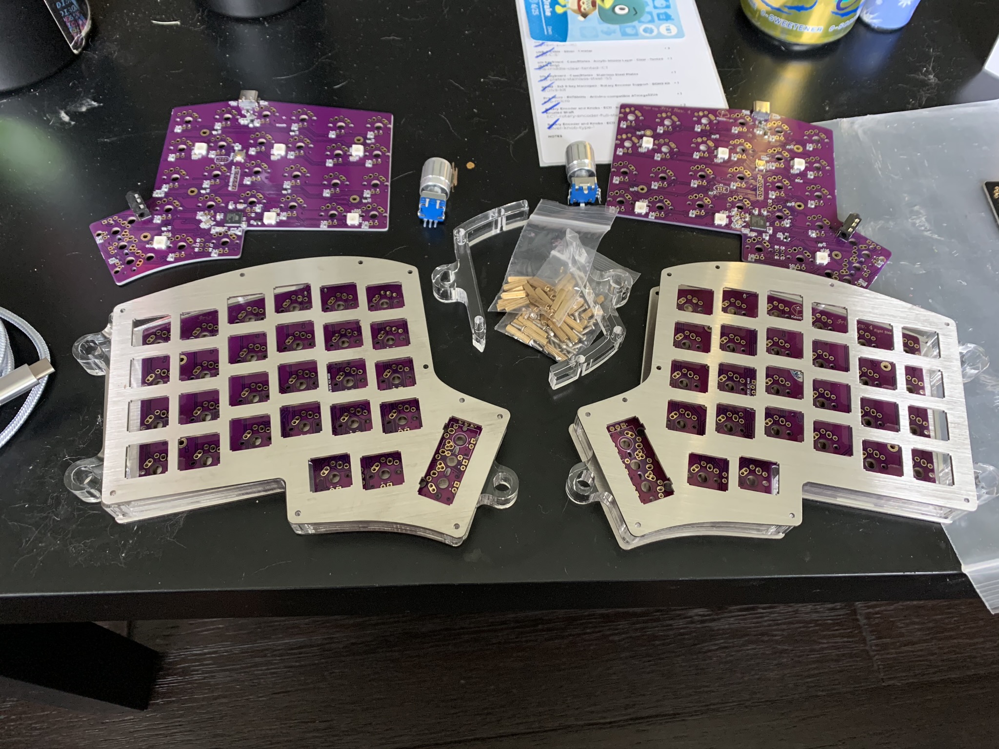
- Iris Rev 4 PCBs
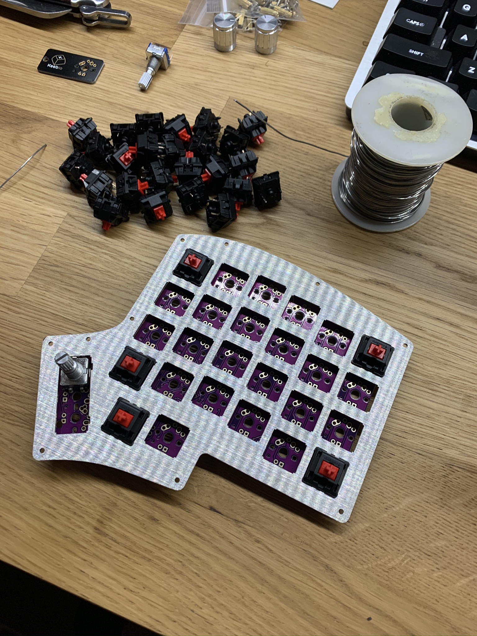
- Cherry MX Red Switches
- Stainless Steel plates
- Acrylic Middle Layer, tented
- Same link for the plates, select a different product.
- Silver w/ Sheath TRRS Cable
- USB-C cable
- Rotary Encoder
Total: ~$200. This could certainly be much cheaper but I went with the stainless steel plates which aren’t cheap. 3D printing or otherwise building my own case would have dropped the price significantly.
I ordered two sets of PCBs in case I wanted to make a second one at some point with different switches. I didn’t want to have to wait for another PCB to ship. Of course I learned after I bought all the parts for this keyboard that there are open source PCBs that I could have easily had fabbed. I will likely do that in the future.
Further, I had to download the QMK toolbox and associated firmware for the board. I would have had to do it anyway, but I needed it immediately because of some issues I had with one of the boards that I’ll describe down below. It was also very useful for me to have an ISP programmer for troubleshooting.
Construction
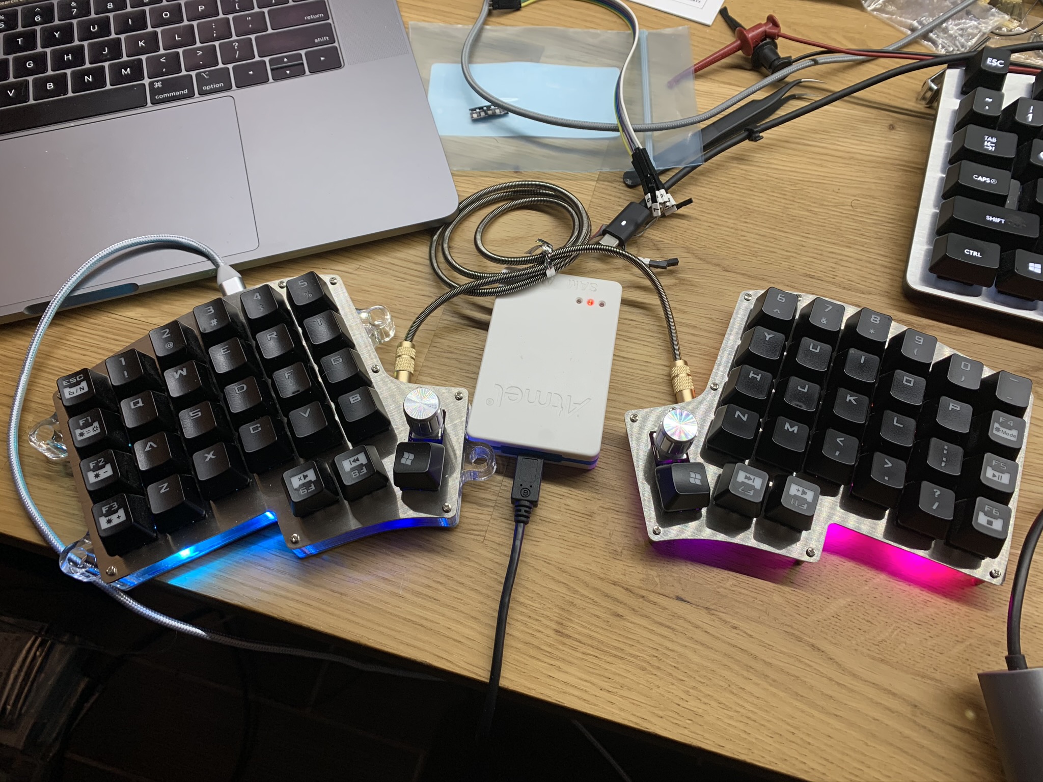
The image above is the finished keyboard (mostly). I don’t have the best keycaps as I cannibalized them from an old keyboard I had. However, it lives!
Initial
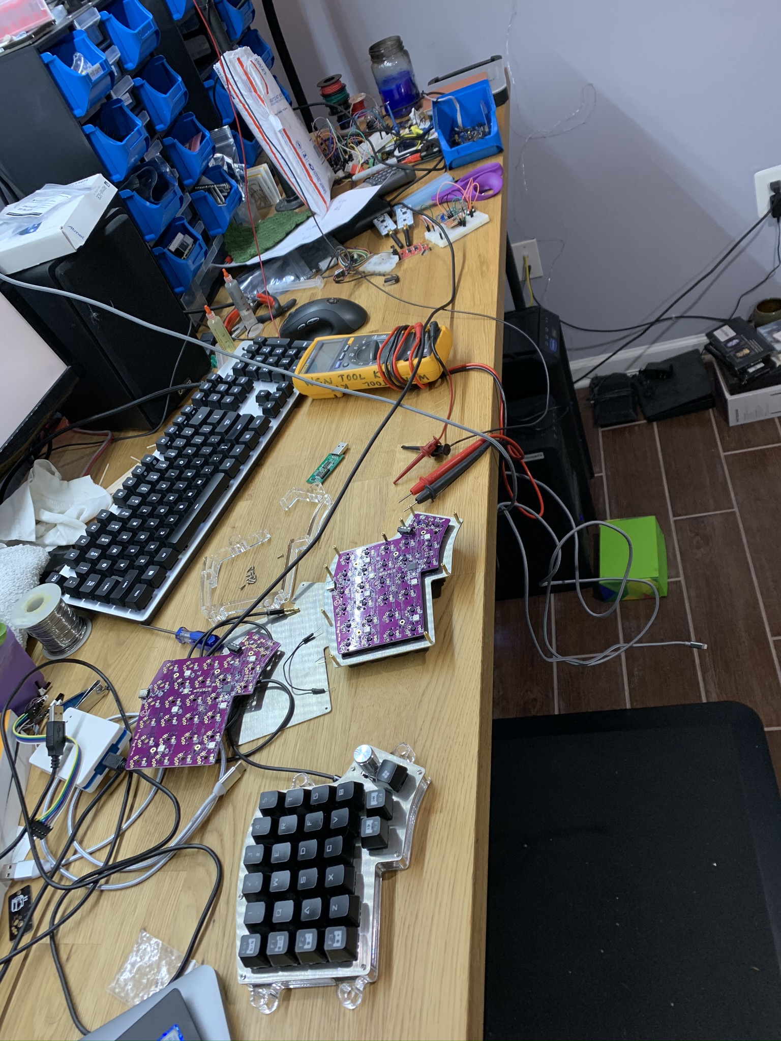
I received all the components for the keyboard after about a week. It was pretty straightforward to assemble, and I have a lot of experience soldering and tinkering with AVR devices so it wasn’t anything challenging.
I followed the build guide on the Iris website and had little trouble following it.
I accidentally soldered the rotary encoder to the wrong side so I had to de-solder and swap it. Afterward I made sure to place the components on the correct side of the board :P
The keyboard switches have to be shoved through the plate and then soldered onto the PCB, which creates a kind of sandwich. Soldering all these switches took a lot of time so it was important to get it right.
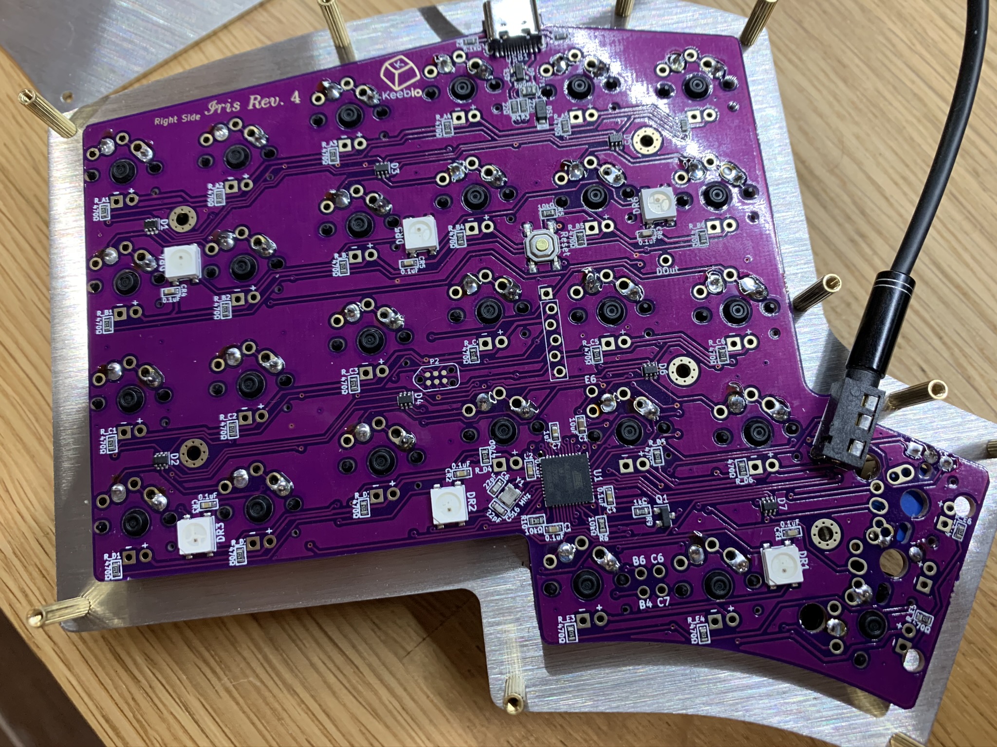
Completed Build and Hardware Issue

After a whole lot of soldering, and the purchase of a TRRS cable that I neglected to obtain, only half of the board worked T_T. As seen in the previous image, the left side of the board is lit up, and provides input to the connected machine, but the right side is completely dead.
Troubleshooting
These boards come pre-flashed with the firmware for the keyboard, which includes a bootloader. The bootloader allows the chip to be programmed through USB rather than through the ISP. I downloaded the QMK toolbox to see if the board is responsive at all. When the USB was plugged into the left side of the board, the Toolbox app would indicate that a DFU device was present. However, when the USB cable was connected to the right side, QMK Toolbox produced no change or message. At this point, it seemed like the MCU was dead or otherwise disabled. In any case, it didn’t have a working bootloader.
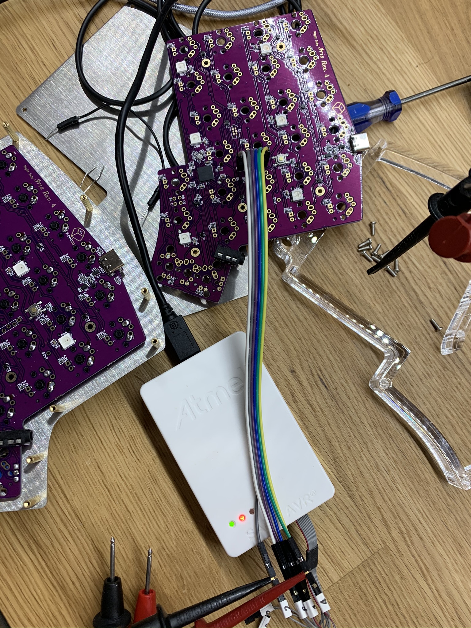
As I have several ISP programmers I decided to take a look at the chip itself to see if I could get any response directly. I used Avrdude to do an initial inspection of the chip and received problematic information. The device signature was not providing the correct byte array for the chip:
avrdude: Device signature = 0x303030
I decided to see if I could flash the bootloader anyway. I obtained the proper bootloader hex file from the QMK repo and attempted to flash using the following command:
avrdude -c atmelice_isp -P usb -p m32u4 -U flash:w:util/bootloader_atmega32u4_1.0.0.hex:i -F
The Output
avrdude: Short read, read only 0 out of 512 bytes
avrdude: jtag3_edbg_send(): Unexpected response 0xc0, 0x65
avrdude: Short read, read only 0 out of 512 bytes
avrdude: jtag3_edbg_recv(): Unexpected response 0x50

...

avrdude: usbhid_open(): No response from device
After realizing that my MCU was pretty much toast, along with some help from the keeb.io discord, I was able to have a new one sent to me. In the mean time, I decided to see how I could fix the board that I had. If I could replace a couple dollar part, I could save keeb.io from losing a board or spending the time to repair it. I realized pretty quickly that the 16 Mhz crystal oscillator attached to the chip had a pretty substantial dent in it right above the pad.
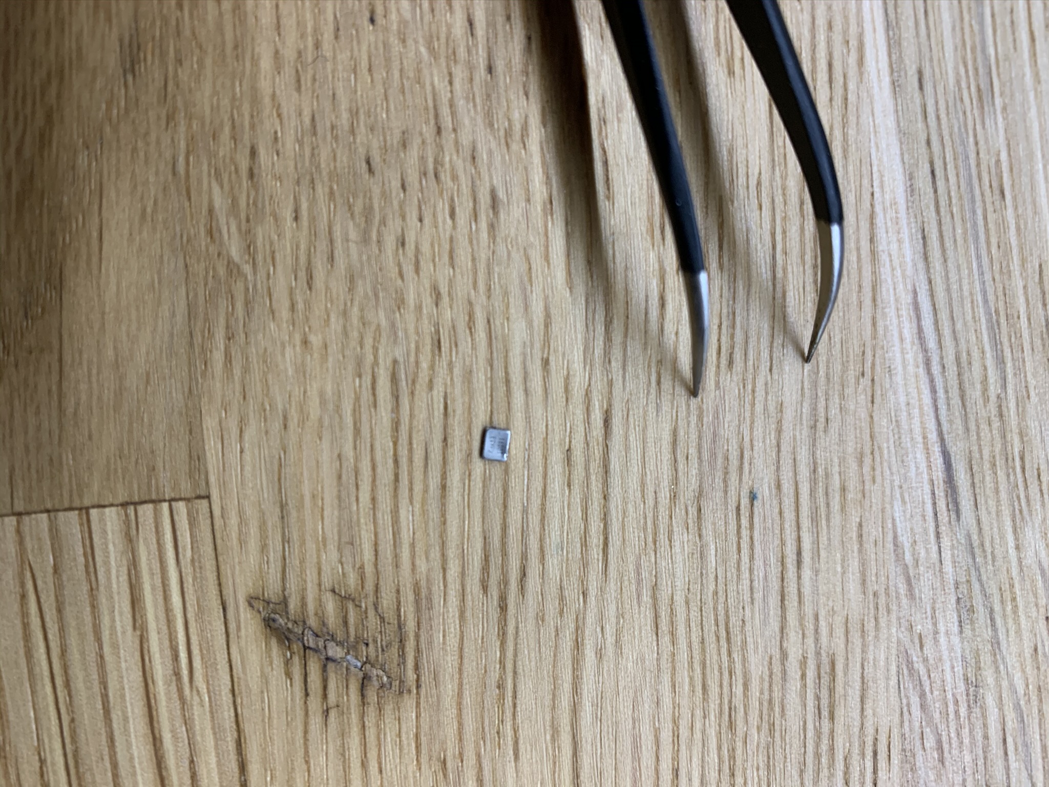
It seemed fairly obvious at this point that either the oscillator or the MCU chip were bad. I immediately placed an order on Digikey for the proper MCU and took a guess at the appropriate crystal. I measured the crystal using a calipers to make sure I obtained one of the proper dimensions in addition to verifying the footprint used in the build. The oscillator was about $.50, so I ordered several in case I destroyed one or two.
A few days later my components arrived and I immediately swapped the crystal. I have a hot air rework machine from Sparkfun so surface mount stuff is super easy to mess with.
And, it worked!
I attached my ISP programmer back to the circuit and saw immediately that replacing the crystal fixed my problem. I imagine since the fuses are set to use an external oscillator that’s why I was getting failing results previously. I flashed the bootloader successfully. Anyway, QMK Toolbox showed that indeed the DFU Bootloader was present and ready to receive some firmware.
Of course it wouldn’t be so easy. I left the ISP programmer plugged in to the board while I was attempting to flash the firmware and kept receiving failures. I thought that since DFU programming was strictly over USB I could leave my ISP connected, or even flash it through there. It turns out that I can only have one connected - the USB. As soon as I disconnected the ISP programmer and unplugged it from my machine, I was able to flash the firmware without any issue.
The RGB LEDs came on instantly and I felt major relief.
Conclusion
Building this keyboard was fun and I look forward to building another one. I haven’t typed on it much since assembling it, but it’s a really nice little keyboard. I ended up pulling out a lot of my embedded development knowledge in order to appropriately diagnose the problem. I could have easily sent this board back to keeb.io and received a new one, but I didn’t for a couple reasons. First, I have a lot of electronics knowledge that made this pretty straightforward for me to troubleshoot. Second, de-soldering all of those switches would have taken hours, which was ridiculous when I knew that the problem was one of two components that would be effortless by comparison to replace.